Gamma Camera & Collimators
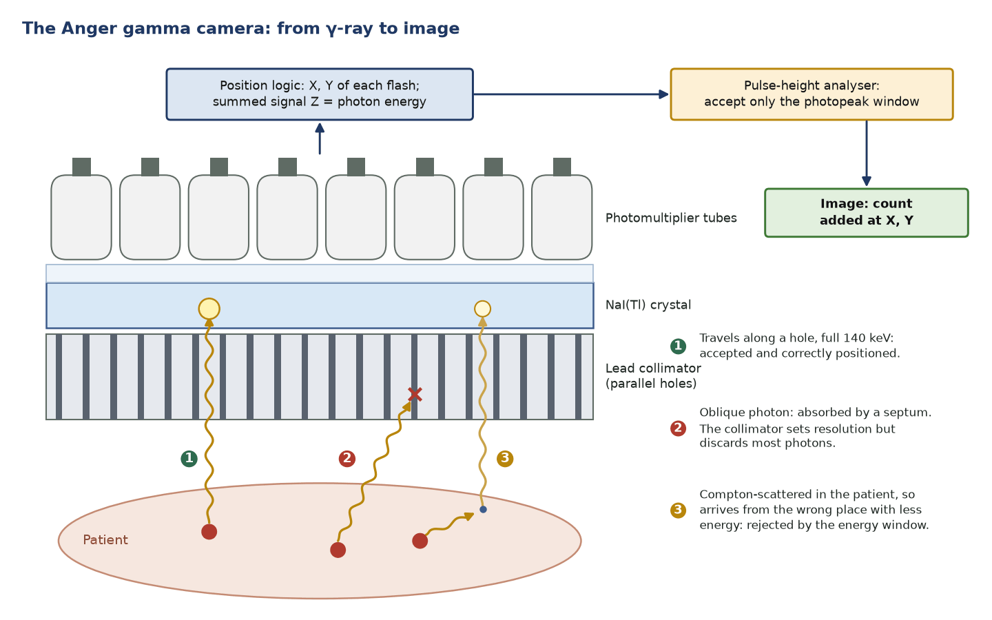
The Anger gamma camera converts γ-rays into images: a collimator selects photon direction, a NaI(Tl) crystal converts them to light, photomultiplier tubes localise and quantify events, and a pulse-height analyser accepts only photopeak energies (typically a 20% window at 140 keV). The collimator is the main determinant of spatial resolution and sensitivity — and the two always trade off.
Because γ-rays cannot be focused, a lead collimator absorbs obliquely travelling photons so only those near-perpendicular reach the crystal. This defines geometric resolution but discards most photons, so sensitivity is low.
- NaI(Tl): density 3.67 g/cm³, decay time about 230 ns, about 38 light photons per keV, hygroscopic.
- A 9.5 mm (⅜ inch) crystal stops about 90% of 140 keV photons; thinner 6.4 mm crystals suit low-energy cardiac work.
- Intrinsic resolution of current cameras 3–4 mm FWHM (resolves 2.5 mm bars); energy resolution 9–10% at 140 keV (AAPM Report 177).
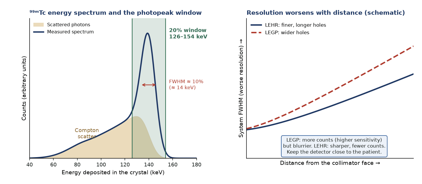
- 20% window at 140 keV = 126–154 keV (±10%).
- Septa are designed for less than about 5% penetration at the rated energy.
- Example LEHR (Siemens Symbia): hexagonal holes 1.11 mm, septa 0.16 mm, length 24.05 mm; system resolution ≤7.5 mm at 10 cm; sensitivity 202 cpm/µCi (≈91 cps/MBq).
- Count rate: about 10% loss at 80 000–100 000 observed counts/s on current cameras (AAPM Report 177).
Percent energy window → keV range
Given. ⁹⁹ᵐTc 140 keV photopeak with a 20% window.
- Half-width = 0.10 × 140 = 14 keV.
- Lower = 140 − 14; upper = 140 + 14.
Answer. Window = 126–154 keV.
Geometric efficiency of a point source
Given. Point source on the axis of a 20 cm diameter detector (radius r = 10 cm) at distance R.
- Exact: f = (1 − cos θ)/2 with tan θ = r/R.
- R = 10 cm: θ = 45°, f = (1 − 0.707)/2 = 0.146. The approximation r²/4R² would give 0.25, far too high.
- R = 50 cm: exact f = 0.0097; r²/4R² = 0.010, now adequate.
Answer. 14.6% at 10 cm and about 1% at 50 cm. The r²/4R² (inverse-square) form holds only when R ≫ r.
Why the collimator dominates system resolution
Given. LEHR: hole d = 1.11 mm, length L = 24.05 mm; µ(Pb, 140 keV) ≈ 27 cm⁻¹; source 100 mm from the face; intrinsic resolution 3.5 mm.
- Effective length L_eff = L − 2/µ = 24.05 − 0.74 = 23.3 mm.
- R_coll ≈ d(L_eff + b)/L_eff = 1.11 × 123.3/23.3 = 5.9 mm.
- R_sys = √(3.5² + 5.9²) = 6.9 mm.
Answer. About 7 mm, close to the ≤7.5 mm specification (which also includes the gap to the crystal). Halving the intrinsic term would improve R_sys by only about 0.6 mm.
Detector chain
- Collimator → NaI(Tl) crystal (scintillation) → photomultiplier tubes → position logic → pulse-height analyser.
- Energy resolution of about 9–10% FWHM at 140 keV allows scatter rejection with a 15–20% photopeak window.
- Thinner crystals improve intrinsic resolution at low energy; thicker crystals improve sensitivity at higher energy.
Collimators
| Collimator | Property | Typical use |
|---|---|---|
| Low-energy high-resolution (LEHR) | Best resolution, lower sensitivity | Most ⁹⁹ᵐTc imaging |
| Low-energy general-purpose (LEGP/LEAP) | Balanced | Dynamic and higher-count studies |
| Medium-energy | Thicker, longer septa | ¹¹¹In, ⁶⁷Ga, ¹⁷⁷Lu; quantitative ¹²³I |
| High-energy | Thickest septa | ¹³¹I |
| Pinhole | Magnifies small structures | Thyroid, paediatric hips |
| Converging/diverging | Alters field of view | Selected applications |
Resolution & sensitivity
- System resolution combines intrinsic (crystal and electronics) and collimator (geometric) resolution in quadrature; beyond a few centimetres the collimator term dominates.
- Collimator resolution worsens linearly with distance, so keep the detector close to the patient.
- For a parallel-hole collimator sensitivity is roughly independent of source distance in air, and finer resolution is bought at the cost of sensitivity (efficiency ∝ resolution²).
Pitfalls
- Wrong collimator for the isotope (e.g. low-energy for ¹³¹I) causes septal penetration and star artefacts.
- Off-peak energy windows admit scatter and degrade contrast and uniformity.
- Non-uniform PMT response causes field non-uniformity (ring artefacts on SPECT); daily flood QC detects it, and PMT tuning or new correction maps fix it.
In the clinic — why the physics matters
- Thin crystals reduce light spread and multiple interactions (better intrinsic resolution) but let more high-energy photons pass (lower sensitivity), which is why low-energy cardiac cameras use thin crystals.
- Collimator choice is the core resolution-versus-sensitivity decision: high resolution for detail, general purpose or high sensitivity for fast dynamic studies.
- Collimator resolution is best at the face and worsens with distance, so position the patient as close as possible.
- The energy window, not the collimator, discriminates scatter by energy; the collimator selects photons by direction only.
Parallel-hole collimator families
| Collimator | Design | Rated energy | Typical use |
|---|---|---|---|
| LEHR | Small holes (about 1–1.5 mm), thin septa (about 0.15–0.2 mm) | ≤ ~160 keV | ⁹⁹ᵐTc planar and SPECT |
| LEGP/LEAP | Larger holes, shorter bore | ≤ ~160 keV | Dynamic, first-pass, low-count studies |
| Medium energy | Septa about 1 mm, longer bore | ~300 keV | ⁶⁷Ga, ¹¹¹In, ¹⁷⁷Lu; ¹²³I when high-energy emissions matter |
| High energy | Septa about 2 mm or more | ~400 keV | ¹³¹I |
Common pitfalls & misconceptions
- The collimator rejects photons by direction, not energy: scattered photons that happen to travel along the holes pass straight through, and only the energy window removes them.
- You cannot maximise resolution and sensitivity together; they move in opposite directions with hole geometry.
- A '20% window' means ±10%, not 20% on each side.
- Thicker crystals are not simply better: they raise sensitivity at higher energies but degrade intrinsic resolution.
In depth
- Anger positioning: X = ΣxiSi/ΣSi (similarly Y), and the summed signal Z gives the energy. Energy, linearity and uniformity correction maps then correct local variations in PMT gain and light collection.
- Collimator equations (parallel hole): R_coll ≈ d(L_eff + b)/L_eff and efficiency g ≈ K²(d/L_eff)²·d²/(d + t)², with L_eff = L − 2/µ. Hence g ∝ R_coll², and g does not change with source distance in air.
- System resolution R_sys = √(R_int² + R_coll²). At 10 cm the collimator term (6–8 mm for LEHR) dominates over the 3–4 mm intrinsic term, so the patient–collimator distance matters more than crystal performance.
- ¹²³I emits small amounts of higher-energy photons (e.g. 529 keV, about 1%) that penetrate LEHR septa and down-scatter into the 159 keV window; medium-energy collimators reduce this for quantitative work such as MIBG heart-to-mediastinum ratios.
- Pinhole magnification = f/b (pinhole-to-crystal distance over pinhole-to-object distance); sensitivity falls roughly as 1/b², and objects at different depths are magnified differently.
- The ⁹⁹ᵐTc spectrum also shows an iodine escape peak about 28–33 keV below the photopeak, a Compton edge and backscatter region, and lead K X-rays (about 75–85 keV) when higher-energy sources hit the collimator.
- Semiconductor (CZT) detectors convert photons directly to charge, without PMTs, giving better energy resolution than NaI(Tl) and allowing compact, pixelated cardiac and general-purpose cameras.
- NEMA NU 1 intrinsic tests use a point source at least five UFOV diameters away (AAPM Report 177 accepts four) with low count rates, so that geometry and dead time do not distort the result.
Sources: Cherry, Sorenson & Phelps, 4th ed. (2012) · AAPM Report 177 (2019) · NEMA NU 1-2018 · Anger, Rev Sci Instrum 1958 · NNDC NuDat 3 (¹²³I)
Sources
- Cherry SR, Sorenson JA, Phelps ME. Physics in Nuclear Medicine. 4th ed. Philadelphia: Elsevier Saunders; 2012.
- Anger HO. Scintillation camera. Rev Sci Instrum. 1958;29:27-33.
- National Electrical Manufacturers Association. NEMA NU 1-2018: Performance measurements of gamma cameras. Rosslyn, VA: NEMA; 2018.
- Halama JR, Graham D, Harkness BA, et al. AAPM Report No. 177: acceptance testing and annual physics survey recommendations for gamma camera, SPECT and SPECT/CT systems. College Park, MD: AAPM; 2019.
- Bushberg JT, Seibert JA, Leidholdt EM Jr, Boone JM. The Essential Physics of Medical Imaging. 4th ed. Philadelphia: Wolters Kluwer; 2021.
- Saha GB. Physics and Radiobiology of Nuclear Medicine. 4th ed. New York: Springer; 2013.